Methods and Construction
This project was conceived, analyzed, designed, and built using the constraints put forth to satisfy both the Mechanical and Electrical Engineering departments at Central Washington University. Working within the constraints of the Mechanical Engineering Department, a full mechanical analysis will be done to determine the forces that the structure will experience, as well as the design of the structure itself. To satisfy the requirements of the Electrical Engineering department, a sensor was developed using photosensitive resistors that will detect the orientation of the sun with respect to that of the panels. This sensor will be implemented into a control system that will drive the motor(s) necessary for articulating the panel. In conjunction with this solar sensor, if time allows, an anemometer will be installed to detect dangerous wind conditions so that the control system knows to lock the panels into a “closed” position to avoid wind damage.
Fall quarter will be focused mainly on designing and carrying out proper analyses of the mechanical aspects of the system. Structural analysis of the frame and pivot points will be done using snow, ice, and wind loading conditions. Worst-case scenarios will be used for these analyses. This includes circumstances where there are three inches of ice on the panel, 60 mph winds blowing perpendicular to the panel so that the panel offers the greatest amount of wind resistance, and one foot of heavy wet snow on the panels. It will also be investigated, if time is permitting, whether it might be possible to program certain sequences in the articulation of the panels in order to reduce snow and ice buildup and keep any articulating mechanics clear of ice. This, however, will be considered supplementary to the initial objective of this project, which will be to get a working device fully operational and take performance data of the system overall.
Simultaneously to the mechanical design will be the design of the electrical control systems of the device. It is anticipated that the system will use an Arduino-based microcontroller, with supplemental driver circuits for the stepper motors. There will also be some auxiliary circuitry built for the photoresistor sensor as well. A voltage divider circuit will be solder together on a prototyping shield that will plug directly into the Arduino shield. This photoresistor circuit will be the part of the system that will monitor the position of the sun and allow for the control system to know how to articulate the panel to follow the progress of the sun.
Winter quarter will be devoted to building the proof of concept and getting a working prototype finished before finals week. The building of the proof of concept will be done in stages. The overall frame will be built first. This includes the frame supporting the panel, uprights, base plates, and pivot points. This assembly, once together, can then be further augmented and changed to add the azimuthal pivoting mechanism and the Elevational pivoting axis. The reason for doing the build in this way is that it will reduce the ambiguity and uncertainty of construction-related issues along the way. There is an inevitable level of slop in the assembly of this device in some respects due to the fact that many of the interacting features and dimensions revolve around being mounted in the slots of the aluminum extrusions used in this design. This can be both good and bad. It will allow for the mismatching of dimensions and issues in GD&T to a certain degree, but it may also prove to increase the ambiguity of the assembly process in some respects as well. By building the system in these stages, some parts can be assembled and mounted completely, and then left in a fastened state while other system are being built. This will allow for sub-assemblies to be completed and mitigate the aforementioned dimensional issues.
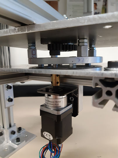
Once the azimuthal pivoting mechanics of the device are assembled, then the motors and gears can be mounted. This is where the slop of the aluminum rail extrusions can be most useful, as the gears will need to be maneuvered and finitely adjusted in order to ensure proper engagement with each other. The motor mounts, motors, gears, and shafts will be installed, and once done, the electrical systems can be installed onto the project. Afterwards, initial tests can begin.
During the manufacturing process, it was decided to make some of the brackets and hardware directly instead of purchasing them in an effort to reduce overall costs. Therefore, all the L-Brackets will be manufactured in the Fluke Machining Lab. Eight of these brackets will be used to mount the base plates to the uprights of the structure, and require custom hole patterns that differ from the standard L-bracket hole pattern for this t-slot railing. These eight L-brackets will also require further machining to account for spatial limitations on the base plate where they will be mounted.
One of the issues with machining these parts manually is that the aluminum extrusion material that they will be made out of is a 90-degree angled piece, with 3-inch-long walls. This will create some clearance issues for the chuck of the milling machine when trying to countersink the holes nearest the back edge of the brackets. One means of remedying this situation will be to purchase a collet extension that has a smaller profile than the existing chuck so that it can be fed into the confined space of the bracket without interfering with the material. Another issue will be the machining of the top and bottom plates for the azimuthal axis pivoting mechanism. All these holes will require tight tolerances in relation to each other as they will need to remain concentric in order for the pivoting to happen on the central axis as expected. This may prove difficult to achieve as there are many holes in these plates, and all the holes, as well as the turntable and stepper motor have specific tolerances that need to mesh properly to ensure proper functioning of this subassembly. Further complication may come from the plates not being flat or warping in the jaws of the vice or while being drilled. All of these issues will likely exist, and all will have to be addressed effectively in order for the subassembly to be installed and operate properly.
Modifications will likely need to be made to the motor mounts as required. One modification that will likely occur will be to use slots in the mounting bracket rather than holes. This will allow for vertical articulation of the motor, and thus allow for better alignment of the intermeshing gears. By slotting out the hole in the bottom plate where the motor shaft protrudes, horizontal articulation can be allowed as well without negatively impacting the structural integrity of the mounting system itself.


